Your cart is empty
by G. Poszmik, HS Kim, J Choo – Shamrock Technologies Inc
© Copyright 2020, Shamrock Technologies, Inc. All Rights Reserved.
Industrial Production of PTFE
Industrial scale production of polytetrafluoroethylene (PTFE) polymer involves several stages.
First, calcium fluoride (fluorspar) is reacted with sulfuric acid to form anhydrous hydrogen fluoride, which is the key source of fluorine for subsequent reactions.
The other starting material, tri-chloromethane (chloroform) is made by reacting methane with elemental chlorine.
The chloroform is then partially fluorinated with anhydrous hydrogen fluoride to produce chlorodifluoromethane (CHClF2, also called R22), which is then pyrolyzed to become tetrafluoroethylene (TFE) monomer.
The polymerization of TFE monomer is carried out under carefully controlled conditions to form PTFE polymer.
It has been reported that the production of a kilogram of PTFE polymer generates a quantity of CO2 that is roughly ten times that amount. Shamrock decided to investigate the validity of that statement.
Details of the Polytetrafluoroethylene (PTFE) production process[i], [ii]:
- 1. Tri-chloromethane is one of the products formed by the reaction of methane and a mixture of chlorine and hydrogen chloride. The reaction can be performed in the liquid phase at 370-420 K using a zinc chloride catalyst, or, alternatively in the vapor phase, using alumina gel or zinc oxide on silica as a catalyst at 620-720 K.

- 2. Production of chlorodifluoromethane2) Production of chlorodifluoromethaneTri-chloromethane is reacted with anhydrous hydrogen fluoride in the presence of an antimony-based catalyst to give chlorodifluoromethane (R22):

- 3. Production of tetrafluoroethylene (TFE) monomerSince TFE is an explosive gas (bp 197 K), it is usually made when and where required for polymerization so that there is minimum storage time of the monomer between its production and its polymerization. Chlorodifluoromethane is heated in the absence of air, a process known as pyrolysis:
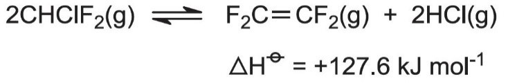
Low pressures (near atmospheric) and high temperatures (940-1070 K) favor the reaction. Steam, preheated to 1220 K, and chlorodifluoromethane, at 670 K, are fed into a reactor. Steam is used to dilute the reaction mixture and hence reduce the reactant partial pressure, and thus the formation of carbon and other by-products. The steam also supplies all the heat required by this endothermic reaction. Very little hydrolysis of reactant and product occurs.
Once formed, the product must be rapidly cooled to 770 K to prevent the reverse reaction occurring and the explosive decomposition of TFE:
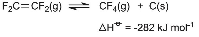
The cooling is done by passing the vapor through a water-cooled heat exchanger, made of graphite to resist chemical attack and thermal shock. Reactor residence time is 1 second.
4) Polymerization of tetrafluoroethylene (TFE) monomer to polytetrafluoroethylene (PTFE)
The monomer is transformed into the polymer polytetrafluoroethylene (PTFE), by radical polymerization. The reaction is carried out by passing TFE into water containing a radical initiator, e.g. ammonium persulfate, (NH4)2S2O8, at 310-350 K and a pressure of 10-20 atm.
Energy consumption and CO2 emission calculations[iii]
To estimate the CO2 emission of PTFE production, a polymerization plant model study was performed. The model plant information was based on a US Fluorochemical production site with PTFE production.
Table 1. Model Fluorochemical production plant info
| Estimated Energy Consumption |
| • 761 kwH/MT fluorochemical production • ~ 96 Therm Natural Gas/MT fluorochemical production |
| Estimated Unit Production: 52,750 MT total fluorochemical production |
| • Anhydrous Hydrogen Fluoride: 12,500 MT • R22: 25,000 MT • Tetrafluoroethylene: 7,750 MT • PTFE: 7,500 MT |
Based on the model plant site, we were able to estimate the total energy consumption for PTFE production. Table 2. Total Energy consumption
| Electric energy |
| 761 kwH x 52,750 MT total production/7,500 MT PTFE Production = 5,400 kwH/MT PTFE |
| Natural Gas |
| 96 Therm x 52,750 MT total production/7,500 MT PTFE Production = 680 Therm/MT PTFE |
Based on above estimated energy consumption, the required amount of electric energy and natural gas can be converted to equivalent CO2 emission [iv], [v], [vi]; Table 3. CO2 emissions for PTFE polymerization
| CO2 Emissions from Electric energy |
| • 5,400 kwH/MT PTFE x 1.10 kg CO2eq/kwH = 5,900 kg CO2eq /MT PTFE or 5.90 kg CO2eq /kg PTFE |
| CO2 Emissions from Natural Gas |
| • 680 Therm/MT PTFE x 5.408 kg CO2eq /Therm = 3,700 kg CO2eq /MT PTFE or 3.70 kg CO2eq /kg PTFE |
Conclusion
Based on the PTFE polymerization model plant study, the carbon emission for PTFE polymer was estimated as at least 9.6 kg CO2eq /kg PTFE. This calculation does not include the energy consumption of mining calcium fluoride, producing sulfuric acid and chloroform which will all add further to the total energy consumption. In other words, using 1 kg of Recycled PTFE instead of virgin PTFE will eliminate at least 10 kg and probably more of equivalent CO2 emission.
References
[i] Ebnesajjad, Sina. Fluoroplastics. Norwich, NY: Plastics Design Library, 2000
[ii] “Poly(Tetrafluoroethene) (Polytetrafluoroethylene) and Other Fluoropolymers.” Essential Chemical Industry, CIEC Promoting Science, 28 Nov. 2018, www.essentialchemicalindustry.org/polymers/polytetrafluoroethene.html.
[iii] Duzick, T. “Calculating the carbon footprint for the manufacture of PTFE.” Shamrock internal investigation paper, June 2015.
[iv] Smith, Roxanne. “EPA Calculator Puts Greenhouse Gas Savings in Everyday Terms.” EPA, Environmental Protection Agency, 15 May 2008, archive.epa.gov/epapages/newsroom_archive/newsreleases/153b0ea448173a4f852573e80050b196.html.
[v] “Greenhouse Gas Equivalencies Calculator.” EPA, Environmental Protection Agency, 15 Oct. 2018, www.epa.gov/energy/greenhouse-gas-equivalencies-calculator.
[vi] Mittal, Moti L., et al. “Estimates of Emissions from Coal Fired Thermal Power Plants in India.” EPA, Department of Environmental and Occupational Health, University of South Florida, Tampa, Florida, USA, Jan. 2012, www.epa.gov/ttnchie1/conference/ei20/session5/mmittal.pdf.